Monoprice Mini Delta Printer
Back in mid-May, I stumbled across a $160
3D printer on Indiegogo. It was being made by Monoprice and was a neat little Delta style printer. I had never worked with a Delta style printer before and I had high confidence that Monoprice would deliver something, maybe even something decent. I thought about it for a few days then pulled the trigger and backed the project.
Fast forward 4 months and the printer finally arrived and on schedule. After printing a litter of the "Good luck cat" (commonly known as Maneki-neko) prints, for which the gcode was supplied on the included micro SD card, I decided to run a few tests.
 |
| Maneki-neko test prints on display in the office of our company's Crazy Cat Lady. |
Long prints:
The early recipients complained of frequent lockups and shifting layers, so I printed a much
larger cat, of course. The one on the SD card takes one hour and fifteen minutes to print. My large cat print took eight hours and forty one minutes to print. No shifted layers, no signs of overheating. Yay!
The print turned out quite well, with the few defects being attributable to my choosing poor print settings.
The Teardown:
OK, it works well (but quite loud). By this time, I have had the printer for nearly 24 hours and could not resist digging into it to see how it is constructed. I wanted to see the design and quality of the build.
Before ripping anything open, here is the extruder. It is a simple pinch wheel design, with the hobbed gear mounted directly on the motor shaft. A simple spring loaded "L" bar provides the tension of the freewheel against the filament. I will be amazed if this lasts a year, but it is interesting seeing how well such a cheap and minimalistic extruder actually works.
Now for the part you have been waiting for...
 |
| Ripped apart with the build plate and heater (upper left) removed. Bottom cover is Center Left. Display is Center bottom. The controller board is still installed in the printer, attached to the upper base plate. |
 |
| The view of the front right leg, which has a flexible plastic piece to provide cable management and keep it looking tidy. Very nice touch. |
 |
Rear view of the display unit. You can see the integrated PCB wifi antenna clearly. It appears that it should be easy to install an external antenna jack, if needed.
Note the flex cable has a ground pad sticking up, which matches with a ground pad on the PCB, but they are not soldered together. Others have reported that this is the same for them as well. I suspect they found that using the header socket was cheaper than doing a direct solder from the PCB to the flex cable and skipped the ground contact.
|
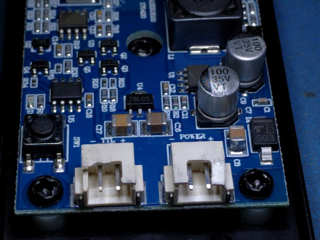
 |
You can see the white connector has a hand mod to it and has a solder blob covering 4 tracks. This appears to be used for the LCD backlight. Also note the choice of installing capacitors on the flex cable itself. Not sure how I feel about that choice.
I also found about 4 loose solder balls of large size, stuck in the flux residue on the back of the board. If the board gets warm, the flux residue could soften and release these solder balls into other components on the board, potentially causing a short and permanent damage to the PCBA. |
 |
| The driver board has a STM32F070CBT6 ARM processor, 4 HR4985 (A4985 clones. Details at the bottom of this page) stepper drivers, set for 1/8 microstepping. The stepper drivers are covered by an ineffective heatsink, which I believe to be a major cause of the overheating problems people have been facing. |
 |
| Another view of the controller. |
 |
Closeup of the stepper drivers. Note that there is white thermal compound on the bottom driver IC, but not the other two. Due to process variations, the two end ICs were slightly higher than the two center ones, when the heatsink was attached (via thermal adhesive strip) only the two end ICs made solid contact. The two center ICs made only a minor impression in the thermal interface material.
My theory is that sometimes the ICs don't make contact at all, with the heatsink, so the heatsink actually blocks the air and PREVENTS cooling on those ICs. Simply pressing the heatsink firmly against the ICs, would likely fix the overheating issues people have been having. |
 |
| Hmmm, ChengX capacitors. This is known as one of the cheapest and worst brands available. I expect to see lots of failures due to this guy... |
My Modifications:
I always like having a removable buildplate. It makes maintenance so much easier. With this in mind, I chopped the power and thermistor wires about 4 inches from the plate and installed a molex connector.
 |
| Modified buildplate heater cable. I installed a molex connector so I could easily remove the plate for maintenance. |
 |
| The fan was quite noisy and had poor airflow due to the stamped honeycomb fan grill on the bottom of the case. I used a die punch to cut out the offending honeycomb and installed a proper fan grill. |
 |
| Vibration of the printer was being amplified by the surface it was sitting on. To combat this, I made 3 feet from a chunk of Sorbothane. This helped a great deal, but the printer is still quite loud. These feet have the added benifit of raising the printer up about 1/2 inch, this provides better airflow for the cooling fan. |
My plans:
Many of these ideas came from the MP Mini Delta Owners Facebook group.
- The original A4985 stepper drivers have a feature to reduce noise from the motors, I am not sure if these clones have this implemented. I am going to order some replacements and see if there is any improvement in the noise. I'll x-ray the PCBA and get better photos when I do this mod.
- The bearings are not overly loud, but not quiet. I plan on replacing them with IGUS bushings.
- Install vibration dampeners between the stepper motors and their mounts.
- Install white LEDs inside the front two risers, to illuminate the print.
- Replace the single stepper IC heatsink with 4 separate heatsinks to allow proper cooling of the ICs. I haven't had any problems yet, but I have not tried printing when there is a higher ambient temperature.
- Replace the BuildTak clone print surface with a 5" round mirror (already done, testing...)
- Make an inclosure so I can print ABS.
Stepper Drivers:
The HR4985 is a clone of the A4985. In fact, the translated text from the datasheet looks like it was taken directly from the A4985 datasheet.:
https://www.allegromicro.com/~/media/Files/Datasheets/A4985-Datasheet.ashx
Datasheet for HR4985 stepper driver
http://www.heroic.com.cn/uploadfile/1602/05094248.PDF
English translation of the datasheet (courtesy of Google Translate):
HR4985 is an easy-to-use micro-stepper motor driver with internal integrated decoder. It is designed to enable bipolar stepper motors to operate in full, half, 1/4 and 1/8 stepping modes. The stepping mode is selected by the logic input MSx. Output drive capacity of 35V and ± 1A. HR4985 contains a current regulator that operates at a fixed turn-off time in slow or mixed attenuation mode.
The decoder is the key to HR4985 ease of implementation. With STEP a simple input of a pulse can make the motor to complete a step, eliminating the need for phase sequence, high-frequency control lines and complex programming interface. This makes it more suitable for applications where there is no excessive complexity of the microprocessor or the microprocessor.
During the stepping operation, the HR4985's internal circuitry automatically controls its PWM operation to operate in fast, slow and mixed attenuation modes. In the mixed attenuation mode, the device will initially switch to a fast decay after a period of time
Slow decay mode until the fixed off time ends. Hybrid attenuation mode control not only reduces the noise generated when the motor is working, but also increases the accuracy of the step, while reducing the system power consumption.
The internal synchronous rectification control circuit improves power consumption during PWM operation. The internal protection circuit includes: with hysteresis overheat protection, undervoltage lockout and overcurrent protection. No special power-up sequence is required.
HR4985 currently offers a patch package: QFN-24 package with exposed pad, can effectively improve the thermal performance, and is lead-free products, lead frame with 100% tin plating.
Features
● Low on-resistance RDS (ON)
● Automatic detection and selection of current decay mode
● Supports slow decay and mixed decay mode
● Reduce the power consumption of the synchronous rectification function
● Internal undervoltage lockout
● Overcurrent protection
● Compatible with 3.3V and 5V logic levels
● QFN package
● Thermal shutdown circuit
● Ground short circuit protection
● Load short circuit protection
● Low current sleep mode, <10uA


Comments
Post a Comment